nuevo blog
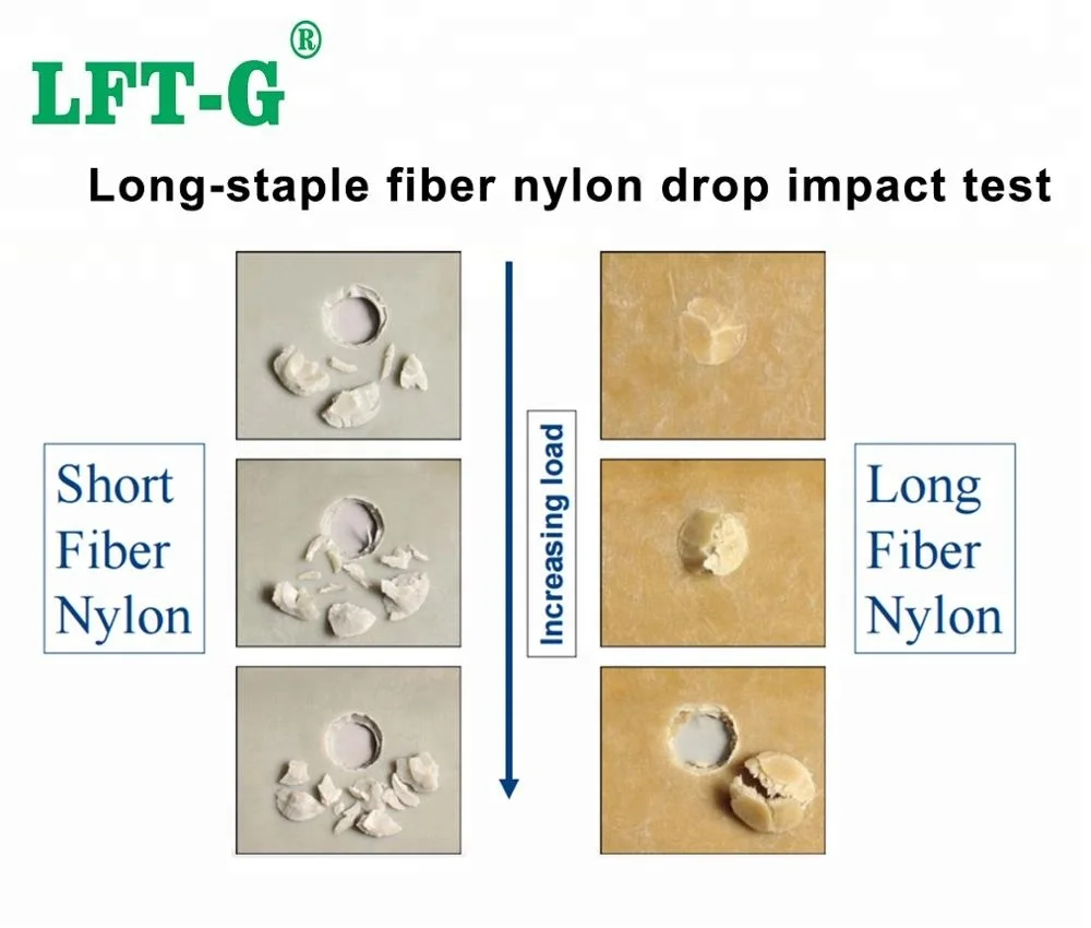
La misma formulación de PA66, la misma carga convencional de fibra de vidrio corta, pero la resistencia a la tracción de la pieza moldeada por inyección es solo la mitad que la de la pieza moldeada por compresión.
El ingeniero de materiales estaba desconcertado: si las materias primas y el contenido de fibra son exactamente los mismos, ¿por qué existe una diferencia tan grande en el rendimiento?
La respuesta se resume en solo dos palabras:longitud de la fibra.
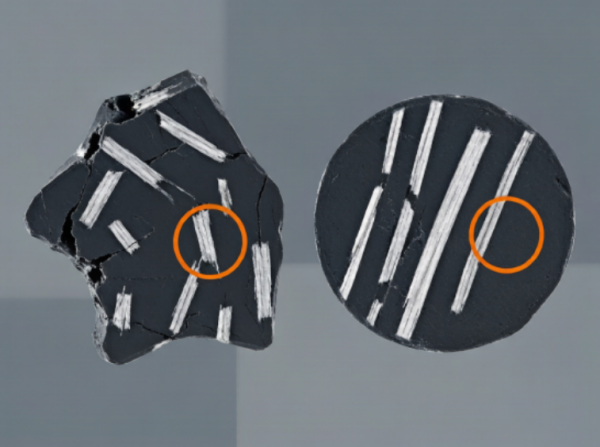
Durante el moldeo por inyección, las fuerzas de cizallamiento de alta velocidad dentro del husillo pueden romper las fibras de vidrio hasta una longitud promedio de tan solo200–400 μmPor el contrario, el proceso de moldeo por compresión más suave permite que las fibras de vidrio conserven longitudes de2–4 mm o incluso más.
El efecto de refuerzo de las fibras de vidrio depende fundamentalmente de laRelación de aspecto de la fibra (L/D)Cuanto más larga sea la fibra y mayor sea su relación de aspecto, más eficientemente se transferirá la tensión entre la matriz de resina y las fibras, lo que en última instancia aumentará el límite de resistencia del material compuesto.
El método de procesamiento corta las fibras.La longitud de la fibra determina el límite de rendimiento.
En 1965, Kelly y Tyson propusieron el modelo de extracción de fibra única, que desde entonces se ha convertido en uno de los fundamentos teóricos de los materiales compuestos reforzados con fibras. Su ecuación central es notablemente simple:
dóndeσces la resistencia del material compuesto,σmes la fuerza de la matriz,Vfes la fracción de volumen de fibra, yσfes la resistencia de la fibra.
Mide el efecto de la longitud de la fibra en la transferencia de tensión. CuandoL > Lc, η se aproxima a 1. CuandoL , η disminuye drásticamente.
Mide el efecto de la orientación de las fibras. Para fibras perfectamente alineadas, η₀ = 1; para una distribución aleatoria en el plano, η₀ = 0,375; y para una distribución aleatoria tridimensional, η₀ = 0,2.
La tensión de cizallamiento en la interfaz fibra-matriz debe actuar sobre una longitud de fibra incrustada suficiente para transferir eficazmente la carga de la matriz a la fibra.
dóndedes el diámetro de la fibra yτes la resistencia al corte interfacial.
Ejemplo de PA66 reforzado con fibra de vidrio
sf ≈ 3400 MPa | re ≈ 13 μm | τ ≈ 30 MPa
Lc ≈ 740 μm
En el modelo Kelly-Tyson,τdetermina la longitud crítica de la fibraLcCuanto mayor sea la resistencia al corte interfacial, menor será la longitud crítica de la fibra, lo que permite que las fibras más cortas soporten las cargas de forma más eficaz.
Por ejemplo, para el PP reforzado con fibra de vidrio, el uso dePP-g-MAHpuede mejorar significativamente la adhesión interfacial y reducir la longitud crítica de la fibra.
Muchos fabricantes de compuestos se centran principalmente enContenido de fibra de vidrio (% en peso)mientras mira hacia adelantelongitud de la fibraEste es uno de los mayores conceptos erróneos sobre los plásticos reforzados con fibra.
La distinción fundamental entreFibra de vidrio larga (LGF)yFibra de vidrio corta (SGF)Por lo tanto, no se trata simplemente del contenido de fibra, sino de la capacidad de mantener una relación de aspecto de la fibra suficientemente alta después del procesamiento.
| Componente | Dosificación | Función |
|---|---|---|
| PA66 | Componente principal | Matriz |
| fibra de vidrio corta | Componente secundario | Reforzamiento |
| Dimensionamiento de fibra de vidrio compatible con PA | Según sea necesario | Modificación interfacial |
| Matriz | Sistema de acoplamiento recomendado | Mecanismo |
|---|---|---|
| PP / PE | PP-g-MAH | Mejora la unión interfacial entre la matriz de poliolefina y la fibra de vidrio. |
| PA / PET | Dimensionamiento de fibra de vidrio compatible con Matrix | Mejora la adhesión fibra-matriz |
| Epoxy | epoxi silano | Promueve la interacción química con la matriz epoxi. |
Compruebe ellongitud real de la fibraEl análisis SEM de la superficie de fractura puede revelar una rotura excesiva de las fibras.
Compruebe el diámetro de la fibra de vidrio, el tratamiento superficial, la velocidad del tornillo y la temperatura de procesamiento.
La carga excesiva de fibra puede causarmala dispersión y aglomeración, creando puntos de concentración de estrés.
Más fibra no significa automáticamente un mayor rendimiento.
El objetivo real es preservar una longitud de fibra suficiente y construir una interfaz fibra-matriz resistente para que las fibras puedan soportar la carga de manera efectiva.
Desde PP-LGF y PA66-LGF hasta soluciones LCF de alto rendimiento, nuestro equipo técnico puede ayudarle a seleccionar la longitud de fibra, el contenido de fibra y la matriz polimérica adecuados para su aplicación.
Analice sus requisitos de materiales.Síguenos :


-- Obtener actualizaciones con los últimos temas

 correo electrónico
 español
 English
 français
 Deutsch
 русский
 italiano
 português
 العربية
 日本語
日本語 한국의
한국의 中文
中文